
Views: 0 Author: Site Editor Publish Time: 2026-09-15 Origin: Site


Working with Nickel-Titanium (NiTi) alloys presents distinct metallurgical hurdles on the shop floor. You have to maintain precise phase transformation temperatures while preventing material fatigue during aggressive machining cycles. Medical device OEMs face a specific operational challenge here. They must scale production volumes while strictly controlling the Heat-Affected Zone (HAZ), achieving flawless surface finishes, and meeting stringent FDA and MDR biocompatibility standards. Mastering the end-to-end nitinol stent manufacturing workflow is the only way to clear these hurdles. This process starts with verifying raw material purity and ends with multi-stage electropolishing. Controlling every variable along this path mitigates regulatory risk, drastically reduces scrap rates on the production line, and ensures long-term clinical efficacy for the final implant.
Material integrity dictates yield: Success begins with high-purity medical-grade NiTi alloys and tubing that meets strict concentricity and inclusion limits before any cutting occurs.
Thermal management is non-negotiable: Fabrication methods (like femtosecond laser cutting) and shape-setting protocols must be tightly controlled to preserve the alloy’s superelasticity and target Austenite finish (Af) temperature.
Surface finishing drives biocompatibility: Multi-stage electropolishing is required to remove micro-burrs, eliminate the titanium oxide layer, and prevent in vivo corrosion or thrombosis.
Partner evaluation requires vertical integration: OEMs should prioritize contract manufacturing partners capable of handling cutting, shape-setting, and metrology under one roof to minimize supply chain risk and dimensional drift.
Table of Contents

Choosing pure nickel and titanium forms the foundation of a reliable implant. Vacuum Induction Melting (VIM) and Vacuum Arc Remelting (VAR) processes are standard practice for medical-grade alloys. These advanced melting techniques minimize oxygen and carbon inclusions within the alloy matrix. Non-metallic inclusions act as stress concentrators during cyclic loading inside the human body. They are the primary culprits for downstream fatigue failures in the final device. Multiple remelting cycles ensure a homogeneous microstructure across the entire ingot. This homogeneity prevents localized weak points that could compromise the structural integrity of thin-strut designs during deployment.
Raw NiTi must comply with strict specifications, primarily ASTM F2063. This standard dictates the exact chemical composition required for medical implants, capping carbon and oxygen levels at 0.05 percent maximum. Self-expanding cardiovascular or peripheral stents require a highly specific nickel-to-titanium ratio. Typically, this falls around 50.8 atomic percent nickel. Even a 0.1 percent deviation in this ratio drastically alters the transformation temperatures of the final product. Maintaining tight compositional control ensures the material behaves predictably during subsequent thermal processing and expands with the correct radial force inside the blood vessel.
Drawing nitinol rods into thin-walled tubing involves harsh manufacturing realities. The material work-hardens rapidly during cold drawing operations. Operators must perform frequent intermediate annealing steps to restore ductility and prevent the tubing from shattering under tension. Tight tolerances for wall thickness and concentricity are non-negotiable on the shop floor. Variations in wall thickness lead to uneven expansion forces when the device is deployed. Deviations in concentricity exponentially increase failure rates during laser cutting. The laser focal point shifts if the tube is out of round, causing incomplete cuts on one side or excessive thermal damage to the inner wall on the other.
Incoming quality control establishes the baseline for all subsequent machining operations. You cannot fix bad tubing downstream. Facilities implement rigorous inspection protocols before releasing raw material to the laser cutting floor.
Differential Scanning Calorimetry (DSC): Technicians run DSC tests to verify the baseline transformation temperatures of the raw tubing. This measures the heat flow associated with phase transitions, confirming the raw material possesses the correct thermal memory profile.
Optical Micrometry: Automated laser micrometers measure the outer diameter (OD) and inner diameter (ID) across the entire length of the tube to verify concentricity.
Visual Surface Inspection: High-magnification cameras scan the inner and outer surfaces for drawing lines, gouges, or embedded contaminants that could interfere with laser cutting.
Metallographic Sectioning: Destructive testing on sample lots verifies grain size and checks for micro-inclusions that might have survived the VAR melting process.
Ultra-short pulse laser cutting dominates the industry for processing nitinol tubing. Traditional nanosecond lasers melt the material, leaving a large Heat-Affected Zone (HAZ) and recast slag that requires heavy post-processing. Femtosecond lasers operate on a completely different physical principle. They rely on cold ablation. The laser pulse duration is shorter than the thermal relaxation time of the alloy lattice. It vaporizes material instantly without transferring residual heat to the surrounding metal. This minimizes the HAZ and prevents micro-cracking in the delicate strut intersections. The result is a highly precise cut with minimal thermal distortion, allowing engineers to design ultra-thin struts for neurovascular applications.
Current industry trends show a divergence in device architectures based on clinical application. Traditional laser-cut slotted tube designs remain standard for many peripheral and coronary applications where high radial force is required. However, braided nitinol wire stents are gaining traction for flow diverters and specific neurovascular uses. Laser cutting offers precise control over complex cell geometries and targeted radial force distribution. Wire braiding provides exceptional flexibility and kink resistance in tortuous anatomy. Braiding requires distinct manufacturing workflows. It relies on complex winding mandrels, 16 to 96 wire carriers, and precise wire tension controls. Each intersection in a braided structure moves independently, requiring different post-processing and termination techniques compared to a rigid laser-cut frame.
Photochemical etching serves as a secondary fabrication method for specific device profiles. This process involves applying a photoresist mask to a flat nitinol sheet. UV light exposes the desired pattern, and aggressive chemical baths dissolve the unprotected metal. The etched flat pattern is then rolled into a cylinder and welded along the seam. This method works well for specific low-profile designs or rapid prototyping of flat patterns. However, it faces severe limitations when attempting to achieve complex, high-aspect-ratio strut geometries. The chemical etchant undercuts the material, making it difficult to maintain sharp, vertical sidewalls compared to the precision of femtosecond laser cutting.
Selecting the right fabrication method requires evaluating multiple dimensions across the production lifecycle. The table below compares the primary approaches used on the manufacturing floor.
Fabrication Method |
Setup Costs & Tooling |
Scalability for High-Volume |
Downstream Finishing Impact |
Ideal Clinical Application |
|---|---|---|---|---|
Femtosecond Laser |
High initial equipment cost, low tooling cost |
Excellent for automated, continuous runs |
Minimal thermal damage, easier electropolishing |
Coronary, peripheral, and neurovascular slotted tubes |
Wire Braiding |
Moderate tooling cost (custom mandrels) |
Good, but requires specialized tension monitoring |
Requires careful intersection cleaning and termination welding |
Flow diverters, highly tortuous anatomy |
Photochemical Etching |
Low initial tooling cost (photomasks) |
High throughput for flat patterns |
Requires secondary rolling, welding, and seam polishing |
Large diameter structural frames, flat implants |
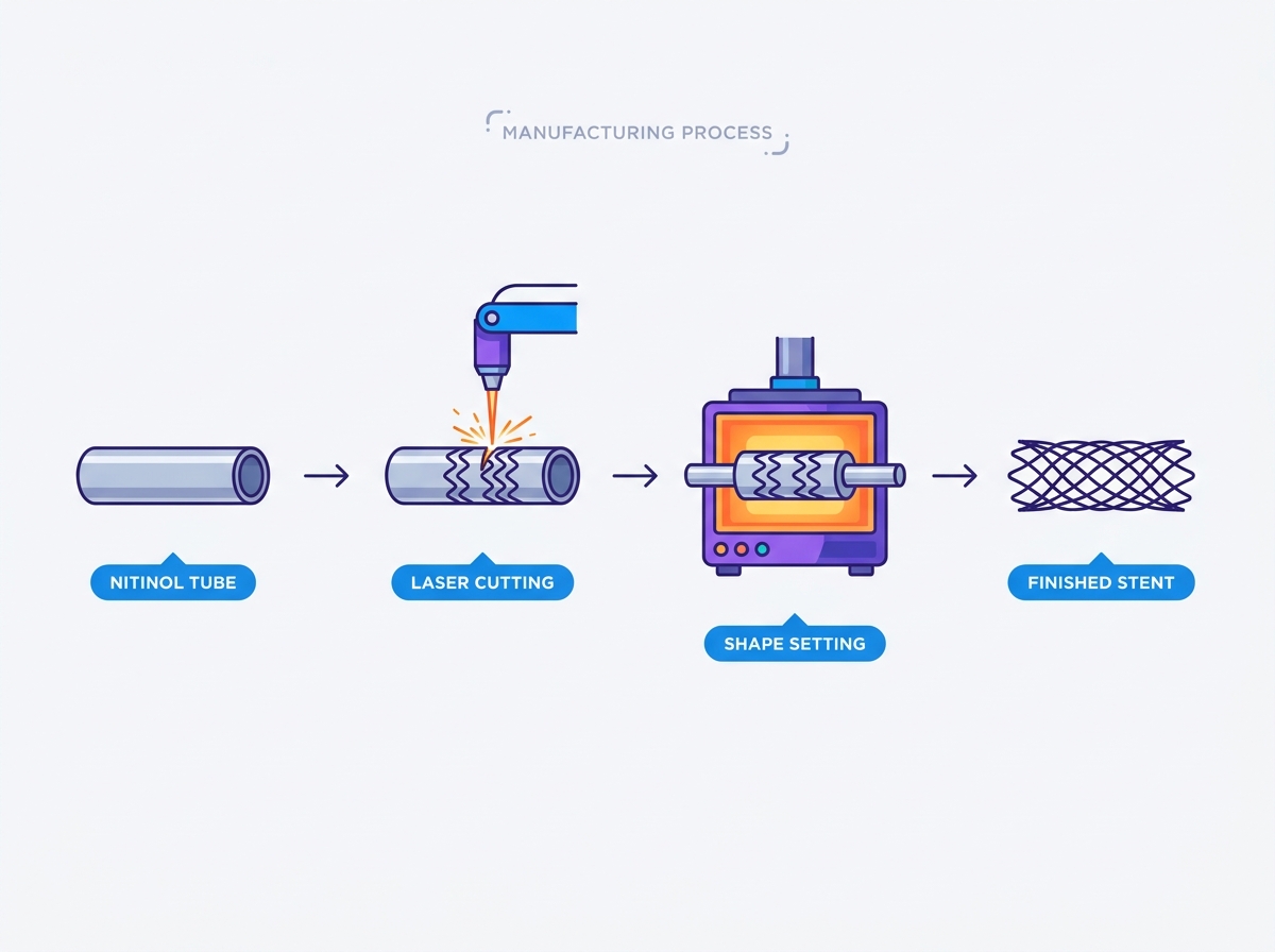
Thermal processing locks in the desired geometry of the device. It works by manipulating the austenite and martensite phases of the alloy. At lower temperatures, the material exists in a deformable martensitic state. Heating it above a specific threshold transforms it into the rigid austenitic state. This phase transformation grants the Nitinol Stent its unique strength and flexibility. Proper thermal programming ensures the device can withstand massive deformation during catheter loading and instantly recover its programmed shape upon deployment in the bloodstream.
Shape-setting requires expanding the laser-cut tubing over progressively larger metallic mandrels. You cannot force a small tube to its final diameter in a single step. Over-expansion leads directly to strut fracture and material tearing. Incremental expansion stages are necessary for complex designs. Operators slide the cut tube onto a small 304 stainless steel mandrel, heat treat it, and then repeat the process with a slightly larger mandrel. This gradual expansion mitigates localized stress concentrations and maintains uniform wall thickness across the entire structure. The mandrels themselves must be precision-machined to account for thermal expansion during the heating cycle.
The actual shape-setting occurs inside precision furnaces, fluidized beds, or molten salt baths. Molten salt baths provide rapid, uniform heat transfer, which is ideal for thin-walled devices. Precise time-and-temperature parameters are required. Typically, these range from 450°C to 550°C. The exact duration depends on the strut thickness, the target diameter, and the specific alloy chemistry. This step shifts the Austenite finish (Af) temperature of the alloy. Continuous monitoring is required during this phase. The goal is to ensure the device remains fully superelastic at human body temperature (37°C). If the Af temperature is set too high, the device will remain sluggish and fail to expand fully inside the blood vessel.
Shape-setting must account for the compressed state of the device. The engineering required to ensure the implant can be safely crimped into a low-profile delivery catheter is extensive. The strut geometry must fold predictably without overlapping, pinching, or exceeding the material's strain limits. Operators use specialized iris-style radial crimping machines to compress the device at controlled low temperatures. Chilling the device forces the material into its martensitic phase, making it easier to deform. The design must guarantee that the device will reliably self-expand upon deployment without losing its programmed geometry or suffering from permanent plastic deformation.
Thermal shape-setting leaves a thick, brittle titanium oxide layer on the strut surfaces. It also leaves a dark thermal scale. This layer is highly prone to flaking and is completely unacceptable for a blood-contacting implant. Removing this layer without altering the delicate strut dimensions presents a major challenge on the finishing line. Operators use a combination of mechanical and chemical approaches. Micro-sandblasting with fine alumina grit physically breaks up the heavy scale. Subsequent acid pickling, usually with a precise blend of hydrofluoric and nitric acid, chemically strips the remaining oxide layer down to the bare metal. Bath temperature and immersion time must be strictly controlled to prevent hydrogen embrittlement.
Electropolishing is the electrochemical process used to smooth the surface at a microscopic level. The device acts as the anode in a specialized acidic electrolyte bath. An electrical current selectively dissolves the microscopic peaks on the metal surface based on viscous layer theory. This process ties directly to clinical outcomes. Reducing surface roughness is mandatory to prevent platelet adhesion, which causes thrombosis. It removes any residual micro-burrs left from laser cutting. Furthermore, electropolishing creates a uniform, highly corrosion-resistant titanium dioxide passivation layer that shields the body from nickel exposure. Facilities often chill the electrolyte to sub-zero temperatures to maintain tight control over the material removal rate.
Analytical methods verify the integrity of the finished surface. Visual inspection under a microscope is insufficient for medical implants. Facilities rely on advanced spectroscopy and electron microscopy to validate the passivation layer.
Scanning Electron Microscopy (SEM): Evaluates the surface topography at high magnification to detect micro-cracks, pitting, or residual slag.
Auger Electron Spectroscopy (AES): Measures the exact thickness of the titanium oxide passivation layer in angstroms.
Depth Profiling: Verifies nickel depletion at the surface. A proper electropolishing cycle leaves a titanium-rich, nickel-free outer layer.
X-ray Photoelectron Spectroscopy (XPS): Confirms the chemical oxidation states of the surface elements to ensure maximum corrosion resistance.
Optical metrology techniques verify strut width, thickness, and overall geometry against the original CAD models. Automated vision systems equipped with telecentric lenses measure hundreds of data points on a single device in minutes, ensuring zero dimensional drift across production lots. Mechanical testing ensures the device performs correctly inside the vessel. Radial resistive force (RRF) testing measures the force the device exerts against the vessel wall to keep it open. Chronic outward force (COF) testing measures the continuous pressure applied over time. Simulated use testing is also mandatory. This verifies the trackability of the device through tortuous anatomy and confirms its crimp profile integrity during catheter delivery.
Implants must survive millions of cardiac cycles without fracturing. Accelerated pulsatile fatigue testing simulates 10 years of human heartbeats. The devices are deployed inside mock silicone vessels filled with a 37°C phosphate-buffered saline (PBS) solution to mimic physiological conditions. High-frequency testing machines pulse the vessels at 30 to 60 Hz, subjecting the struts to continuous cyclic loading. This aggressive testing identifies potential failure points or micro-cracks introduced during manufacturing. Any strut fracture during this 400-million-cycle test constitutes a catastrophic failure. Passing this test proves the structural durability of the design and the integrity of the manufacturing process.
Regulatory submission requires comprehensive, evidence-oriented documentation. Process validation forms the core of this requirement. Installation Qualification (IQ), Operational Qualification (OQ), and Performance Qualification (PQ) protocols must be executed for every piece of equipment on the floor. Traceability is absolute. You must maintain an unbroken chain of documentation from the raw material lot to the finished component. Every thermal cycle, chemical bath concentration, and inspection result must be recorded and tied to a specific serial number or lot code. This rigorous data collection proves to regulatory bodies that the manufacturing process is stable, repeatable, and safe for human application.
Using different vendors for laser cutting, shape-setting, and electropolishing introduces severe risks. Shipping parts between facilities exposes them to contamination and oxidation. It compounds tolerance errors, as each vendor works to their own baseline and measurement standards. Accountability issues arise when a final part fails inspection, leading to finger-pointing between suppliers. A vertically integrated contract manufacturer handles all these steps under one roof. This centralization ensures tight process control, immediate feedback loops between the laser cutting and electropolishing departments, and singular accountability for the final yield.
Next-generation design trends demand advanced manufacturing capabilities. Ultra-thin struts for neurovascular applications require extreme precision during laser cutting and electropolishing to prevent material loss. Integrating radiopaque markers, such as tantalum or platinum-iridium, into the strut structure requires specialized micro-welding or mechanical swaging techniques. You must select a partner capable of handling these complex geometries. Their engineering team must possess deep metallurgical knowledge to adapt standard processing parameters to novel, highly intricate device architectures without compromising the alloy's superelastic properties.
Assess a partner's capacity to transition from rapid prototyping to commercial production. New Product Introduction (NPI) requires flexibility and fast iteration. High-volume production requires rigid stability and automation. A capable partner bridges this gap without process drift. They design custom tooling and automated inspection fixtures early in the NPI phase. This ensures the processes validated during prototyping scale linearly when production volumes increase. Evaluate their capacity for automated laser feeding systems, bulk electropolishing racks, and high-throughput vision inspection machines to ensure they can meet commercial demand.
Successful production requires strict, sequential control of thermal and mechanical stress across the entire manufacturing lifecycle. From the purity of the raw ingot to the final passivation layer, every variable impacts clinical safety. You must prioritize partners who understand these metallurgical realities and possess the in-house capabilities to control them.
Audit your current supply chain to identify fragmented processes and consolidate vendors under a vertically integrated manufacturer.
Request a capability review for your specific CAD files to verify their femtosecond laser and shape-setting tolerances.
Initiate a targeted prototyping run to validate dimensional accuracy and surface finishing quality firsthand before committing to high-volume production.
A: Femtosecond laser cutting stands as the industry standard. It utilizes ultra-short light pulses to vaporize material instantly through cold ablation. This mechanism prevents heat transfer into the surrounding metal, minimizes the Heat-Affected Zone (HAZ), and avoids micro-cracking in delicate strut intersections.
A: Shape-setting involves expanding a laser-cut tube over progressively larger metallic mandrels. Operators heat the assembly in a precision furnace or salt bath, typically between 450°C and 550°C. This thermal processing programs the superelastic geometry into the alloy's memory, allowing it to recover its shape after deformation.
A: Electropolishing removes residual micro-burrs and smooths the surface at a microscopic level. It strips away heavy thermal oxides and creates a uniform, biocompatible titanium dioxide passivation layer. This smooth, passive surface prevents in vivo corrosion and significantly reduces the risk of thrombosis.
A: The Af temperature marks the exact point where the alloy fully transforms into its rigid austenitic phase. It dictates the material's mechanical behavior. Engineers must calibrate the Af temperature so the device remains fully superelastic and exerts the correct radial force at human body temperature (37°C).
A: Manufacturers subject them to accelerated pulsatile fatigue testing inside mock silicone vessels. This simulates 10 years of human heartbeats at high frequencies (up to 60 Hz). Additional mechanical tests measure radial resistive force (RRF) and chronic outward force (COF) to verify structural integrity.


